Setting the taper attachment to cut an accurate taper can be difficult. Once you have
initially set up the taper attachment according to the text, the taper attachment setting
will need to be refined. There are a number of ways to check the taper bar settings for
accuracy.
|
|
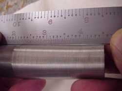
Note: Using a straight edge, check to see that the entire length of the turned area is tapered(Figure 1). There should not be any open space along the straight edge if the entire length is tapered. If the entire length is not tapered, there is still backlash in the taper attachment. Try starting the cut back farther to alleviate all of the backlash. The trial and error method of taper attachment adjusting is acceptable as long as you have plenty of excess stock to work with.
|
|
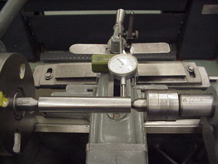
| Now set up an indicator to measure the amount of carriage movement as shown in Figure 3. |
|
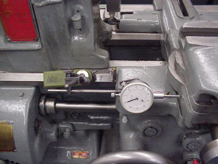
| Move the carriage until the dial indicator on the compound rest begins to read a consistent amount of travel. Set this indicator to zero. Reset the indicator that is keeping track of carriage movement to zero. Move the carriage 1.00 inch. The reading on the cross slide indicator should be that of the required taper per inch divided by 2 (Figure 4). If it is not, move the cross slide extension to the pivot point of the taper bar and adjust the taper attachment accordingly. |
|
|
|
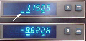
Move the carriage until the X axis readout begins to read a consistent amount of travel. Reset both axis displays to zero. Move the carriage 1.00 inch. Note the X axis diameter coordinate. When the taper bar is set properly, the X axis diameter readout over one inch of carriage travel should be that of the required taper per inch.