Drive Belts
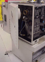
| The drive belts supply power from the motor to the spindle. Access to the drive belts is gained by removing the end guard on the headstock (Figure 1). Make sure that all power is locked out before removing any guards. |
|
|
|
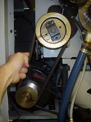
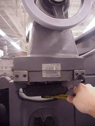
Drive belts come in matched sets and should only be replaced with a matched set of belts. Visually inspect the drive belts for excessive wear and cracking. If you notice that one or more of the drive belts appear to be excessively worn or cracked, bring this to the attention of the instructor. Check the belt tension by applying finger pressure to each belt at a point midway between the two pulleys (Figure 2). For correct tension a deflection of about 3/8 of an inch should be evident in each belt. If the amount of deflection is more than 3/8 of an inch in any one or more of the belts, bring this to the attention of the instructor. |
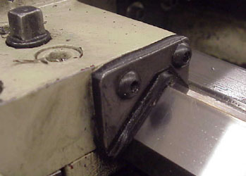
Gib Adjustment
| All lathes employ precision slide ways. The saddle, cross slide, and the compound slide all ride along a box slide way or dovetail slide way. After time the parts that ride along the slide ways begin to wear. To compensate for this wear, machine tools are equipped with adjustable parts called gibs that allow you to eliminate the space that has been created by the wear between the slide ways. (Figure 3). |  Figure 3 A tapered gib located on the cross slide of a lathe |
|
|
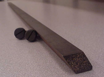
There are two types of gibs, straight gibs and tapered gibs. Straight gibs are adjusted by screws spaced out along the length of the gib. The screws push the gib in to create more contact with the sliding mechanisms (Figure 4). |
| Tapered gibs use two screws. The screws are located in each end of the tapered gib. One screw acts as an adjustment while the other screw acts as a locking mechanism. Because tapered gibs are wider on one end than the other, they slide in or out creating more or less contact between the sliding mechanisms (Figure 5). |
|
Cross Slide Gib Adjustment
| Wear in the cross slide ways must be adjusted by using the screw on the front face of the cross slide. (Figure 6). |
|
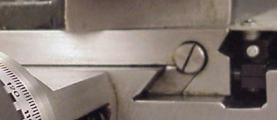
| The procedure is to first loosen the similar gib screw on the rear
face of the cross slide (Figure 6a), then re-tighten the front screw
to lock or adjust the gib in its new position.
After the adjustment, traverse the cross slide over its entire travel to be sure of smooth, even operation. |
|
Compound Slide Gib Adjustment
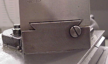
| Wear in the compound slide ways must be adjusted by using the
screw on the front face of the compound slide. (Figure 7).
The procedure is to first loosen the similar gib screw in the rear face of the tool slide, then re-tighten the front screw to lock or adjust the gib in its new position. After making the adjustment, traverse the compound slide over its entire travel to be sure of smooth, even operation. |
|
Wipers Pads
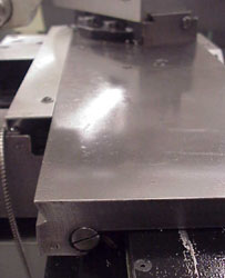
| Most lathes are equipped with wiper pads (Figure 8). Wiper pads
are typically made of felt that will hold oil.
Wipers are designed to keep out small chips and dirt between the slides and the ways. Wipers are saturated with oil to catch the fine particles of dirt or debris before they get between the two sliding surfaces. The wipers should be removed, cleaned, and re-saturated with oil regularly. You should never use compressed air for cleaning a lathe. Compressed air will push the fine particles trapped in the wiper between the mating surfaces of the slides, causing premature wear on these precision surfaces. |
|
Adjusting the Tailstock Clamp
| The lock position of the bed clamp lever on the tailstock is adjustable and should be located before top dead center (Figure 9). |
|
|
|
The lever is adjusted by a self-locking bolt located on the underside of the tailstock front clamp plate and between the bedways (Figure 10). Turn the bolt clockwise to increase the clamping action. Lathes may also be equipped with an auxiliary bolt on the tailstock. This bolt is used to give additional clamping action when required. It does not require any adjustment. |
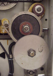
End Gearing and Backlash
| The end gearing on the lathe connects the spindle rotation with
the feed and threading rods (Figure 11).
|
|
|
|
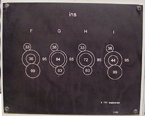
The gears supplied with a lathe allow the operator to obtain an extensive range of feeds, metric threads, threads per inch, module and diametral pitch threads. To cut threads over a broad range, the lathe operator will need to make changes to the end gear train. Basic lathe setup and operation includes being able to properly change the gears in the train. Most lathes are equipped with charts that explain the gear positioning for certain types and ranges of threads (Figure 12). |
| When the proper gears have been selected and set in the gear train, the mounting or clamping bolts should be lightly snugged in place with a strip of paper or feeler stock placed between the gears (Figure 13). |
|
The gears should then be pushed together against the paper shim. The clamping bolts should then be tightened. Remove the shim. The space left between the gears, where the shim was placed, is known as backlash. On most lathes the backlash amount should be between 0.007 and 0.011 inches. If the gears are noisy, more backlash space should be made between the gears. Finish the backlash adjustment by placing a small amount of lubricant on the gear train.