I am looking for: Learn arrow down
I am looking for:
Categories
Categories
The Transistor Switch
The learner views the operation of a transistor switching from saturation to cutoff. A brief quiz completes the activity.
Basic Logic Gates

The learner will understand the operation of the six fundamental logic gates and the inverter by using truth tables, Boolean Algebra equations, switch analogies, and written statements.
By Terry Bartelt Terry Fleischman
Analog Voltmeter Operation
Students follow the procedure to measure voltage with an analog voltmeter. They examine the use of the Function Switch and the Range Switch. A brief quiz completes the activity.
The Magnetron Ignition System

Learners read an explanation of how the Magnetron Ignition System uses a solid state switching component, a step-up transformer, and magnetism to provide a high voltage spark in a one-cylinder combustion engine.
Analog Ohmmeter Operation
Learners follow procedures for measuring resistance using an analog ohmmeter. They examine the use of the Function Switch and the Range Switch and practice reading a non-linear scale. A brief quiz completes the activity.
Ladder Logic Schematic Symbol Flashcards
This interactive object is designed to help learners memorize the schematic symbols used in ladder logic diagrams. Learners quiz themselves using electronic flashcards.
Testing an On/Off Switch

In this learning activity you'll review methods for testing an on/off switch with an ohmmeter and a voltmeter.
Limit Switches
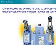
In this animated object, learners examine the basic types of limit switches and how they are used.
Oscilloscope Coupling Switch
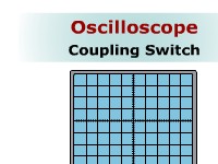
Learners read a description of the function of the coupling switch on an oscilloscope and how its setting affects measurements of DC, AC, and combined voltages. A brief quiz completes the activity.
NOR Gates

In this learning activity you'll review the operation of a NOR gate by using a truth table, a Boolean Algebra equation, a switch analogy, and a written statement.
Internal Circuits of an Inductive Proximity Sensor
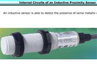
In this animated object, learners examine the operation of various circuits that are internal to the inductive proximity sensor.
Capacitive Proximity Sensors
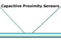
In this animated object, learners examine the operation of a capacitive proximity sensor. A brief quiz completes the activity.
Analog Ammeter Operation
Students examine the procedure to measure current with an analog ammeter. The use of Function and Range switches is explored along with reading the needle position on the meter scale. A brief quiz completes the activity.
NAND Gates

In this learning activity you'll explore the operation of a NAND gate using a truth table, a Boolean Algebra equation, a switch analogy, and a written statement.
Designing a Ladder Diagram
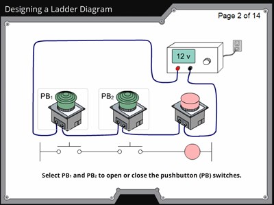
In this animated object, learners examine the design of a ladder circuit that provides manual control to a water pumping system. Students also study modifications to the circuit as the complexity of the system increases.
By Terry Bartelt Terry Fleischman
Selector Switch Labeling
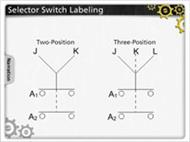
In this animated object, learners examine the method of interpreting the truth tables for two-position and three-position selector switches on ladder logic circuit diagrams.
Exclusive-OR Gates
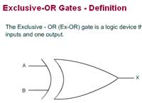
In this learning activity you'll explore how an Exclusive-OR gate operates by using a truth table, a Boolean Algebra equation, a switch analogy, and a written statement.
How Switches Increase Speed
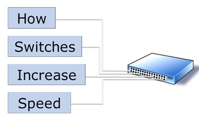
In this learning activity you'll observe how switches are used in local area networks to increase data transmission speeds.
Switches and Hubs

Learners view animations showing how hubs and switches work in local area network configurations.
Finding the Common Connection of an SPDT Switch

In this animated object, learners examine the procedure used to determine the types of terminals on a single-pole, double-throw switch.