I am looking for: Learn arrow down
I am looking for:
Categories
Categories
Superposition Theorem with Complex Numbers
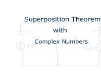
Students read an explanation of "superposition" as a technique for ac circuit analysis. Complex numbers are used.
Series-Parallel Circuit Analysis Practice Problems: Circuit 9
Learners examine a series-parallel circuit and solve 14 problems related to voltage, current and power. A help screen is provided.
Thevenin Resistance: Practice Problems
Students work five practice problems to determine the Thevenin resistance of DC circuits.
Assembling a Circuit from a Schematic Diagram
In this animated object, students examine the steps for wiring an electrical circuit from reading a schematic diagram.
Operation of Full-Wave Bridge Rectifier
In this learning activity you'll explore the operation of a full-wave bridge rectifier circuit.
By Matthew Treu
Voltage, Resistance, and Current Relationships
In this learning activity you'll explain how voltage and resistance in a series circuit affect current flow.
Norton's Theorem
Learners follow the steps for reducing all of the elements of a complex circuit to a single current source and a single source resistance to create a simple circuit. Several examples are given for dc circuits. The conversion between Thevenin and Norton is also presented.
Transfer Functions: The RL Low Pass Filter

Learners read how the transfer function for a RC low pass filter is developed. The transfer function is used in Excel to graph the Vout. The circuit is also simulated in Electronic WorkBench and the resulting Bode plot is compared to the graph from Excel.
Parallel Resistance Practice Problems
Students work practice problems in which the total resistance of the circuit is calculated. Feedback is provided.
Series-Parallel Circuit Analysis Practice Problems: Circuit 10
Learners examine a series-parallel circuit and solve 14 problems related to voltage, current, and power. A help screen is provided.
Kirchhoff's Current Law - Parallel Circuits

In this learning activity you'll explore Kirchhoff's Current Law and view examples of its application.
Series Circuit Analysis Practice Problems Part 1
In this interactive object, learners solve for total resistance and current, the current through each resistor, the voltage across each resistor, and the power dissipated.
Simple Pneumatic Circuits
Learners examine the operation of five pneumatic animated circuits that use directional control valves, pilot lines, check valves, needle valves, and cylinders.
How Adding Parallel Branches Increases Total Current
In this animated object, learners follow an analogy of water flowing through pipes and valves to see how current increases in a parallel circuit as branches are added.
The Transfer Function and Frequency Response of a Low Pass Filter
Students learn how to predict how circuits will respond to varying frequency. They solve for the magnitude and phase angles.
Zener Diode Voltage Regulation

In this animated and interactive object, learners examine how changes in applied voltage affect the current and voltages in a zener diode voltage regulation circuit. A short assessment completes the activity.
Transistor DC Analysis Practice Problems: Circuit #1
Learners analyze a base-biased npn transistor circuit. A "help" screen is available.
Series-Parallel Resistance -- Practice Problems
In this learning activity you'll practice solving for the total resistance of series-parallel DC circuits.
Measuring Current in a Parallel Circuit
In this interactive learning object, students view the ammeter connections for measuring currents in a parallel circuit with three branches on an energy concepts lab board. A brief quiz completes the activity.
Thevenin Voltage: Practice Problems
Students work five practice problems to determine the Thevenin voltage of DC circuits.