I am looking for: Learn arrow down
I am looking for:
Categories
Categories
The Twelve Principles of Lean Manufacturing

Following a "cut the fat" theme, learners click on 12 drawings of pigs to read about the principles of lean manufacturing.
By Weldon Faull
Transistor Fundamentals: Voltage-Divider Biased NPN Transistor

Students view drawings of the dc analysis of a voltage-divider biased NPN transistor.
Leaves

Learners read a general description of the function and structure of leaves and examine drawings and microscopic views. A matching exercise completes the learning object.
The Sense of Hearing (Screencast)

In this screencast, learners examine hearing and balance. Detailed drawings of the outer, middle, and inner ear structures are included.
Screw Threads and Fasteners

You'll practice identifying parts of screw threads and fasteners on a series of drawings.
By Wisc-Online
Transistor Fundamentals: AC Bypass Capacitors
Brain Exercise: Visualization #1
In this interactive object, learners practice their 3D visualization skills by identifying the correct isometric view of an object. Front, side, and top orthographic views are shown.
Schematic Diagram Symbols
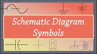
In this learning activity you'll review various types of common components used in electronics and view their schematic diagram symbols.
Brain Exercise: Visualization #2
In this interactive object, learners practice their 3D visualization skills by identifying the correct isometric view of an object.
Parts Make an Assembly
Learners examine the relationship of individual parts in an assembly drawing. Assembly drawing notes, fabricated and purchased parts, and sectional views are explained briefly.
Orthographic Projection #1
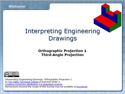
In this interactive and animated object, learners examine orthographic projection and the Glass Box Theory. Front, side, and top view development is demonstrated with pictorial views of each object to help develop 2D to 3D visualization skills.
Title Block Tolerances
Learners examine the use of the tolerances displayed in a title block by calculating the minimum and maximum allowable size of a fabricated part. In a brief quiz, students determine whether a part is usable or should be scrapped.
Brain Exercise: Visualization #3
Learners develop 3D visualization skills by examining front, side, and top orthographic views of objects. Using this information, students select the corresponding isometric view of each object.
Surface Texture Symbols

Learners examine the symbols and values that control surface roughness, waviness, and lay. A brief quiz completes the object.
Interpreting Engineering Drawings: Sheet Sizes

In this animated and interactive object, learners view American National Standard and International Standard sheet sizes. A quiz completes the activity.
Basic Types of Lines Used in Engineering Drawings
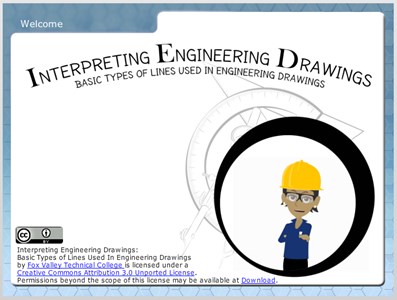
In this highly interactive object, learners associate basic line types and terms with engineering drawing geometry. A quiz completes the activity.
By Kelly Curran Glenn Sokolowski
Basic Types of Dimensioning Used in Engineering Drawings
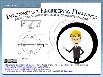
Learners examine the basic types of dimensioning including unidirectional and aligned systems, and linear, aligned, angled, arrowless, chain, datum, chart, tabular, radius, diameter, typical, and reference dimensions.
By Kelly Curran Glenn Sokolowski
Basic Symbols Used in Engineering Drawings
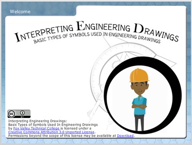
Learners examine the drawing symbols used for counterbore, countersink, spotface, radius, diameter, and depth. In the quiz that completes the activity, they associate these symbols with machining applications.
By Kelly Curran Glenn Sokolowski
Basic Elements of Dimensions Used in Engineering Drawings
In this interactive object, students explore the basic elements and common terms associated with dimensions and leaders. A quiz completes the activity.
Interpreting Engineering Drawings: Title and Revision Blocks (Screencast)
Learners examine the information on a title block and answer questions about that information in an interactive quiz.